Once again it is time to do engine building around the shop. It is a lot faster to do multiples, so six rebuilds were undertaken. A number of people have asked for info, so I am going to put out a light guide for getting an early (1968-1979) engine rebuilt. Not meant to be a definitive guide, you would still want to get one of the Clymer or Haynes manuals for the details.
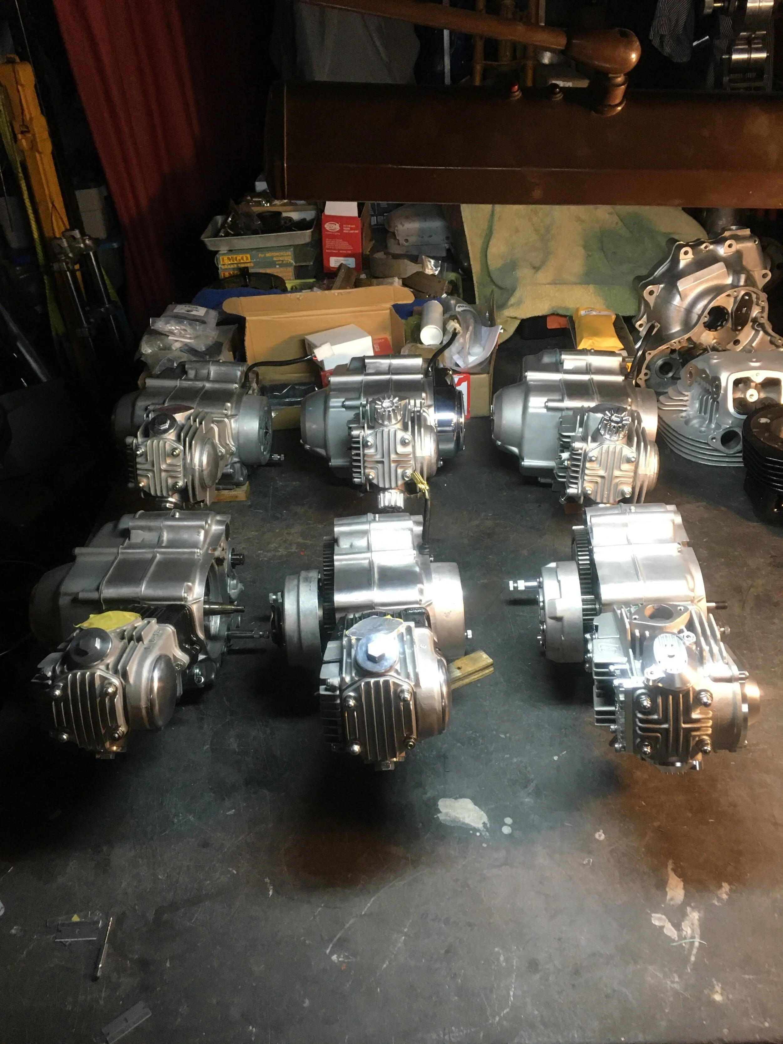
Everything gets rebuilt, replaced, or re-plated. All seals , gaskets, and bearings get replaced. All hardware is re-plated or new. There are four 108cc stroker engines, two with 4 speed trannys, one with a rolling rocker head. All four were given new heavy duty clutches. The two stock rebuilds have new pistons and rings, clutch plates and bearings. The stators and ignition components are restored, and any stripped screws are repaired (although in a rare case, there were no stripped holes on any of the engines.) All the cases were finished as close to the original finish as possible, refinishing any scratches or damage to the surfaces.
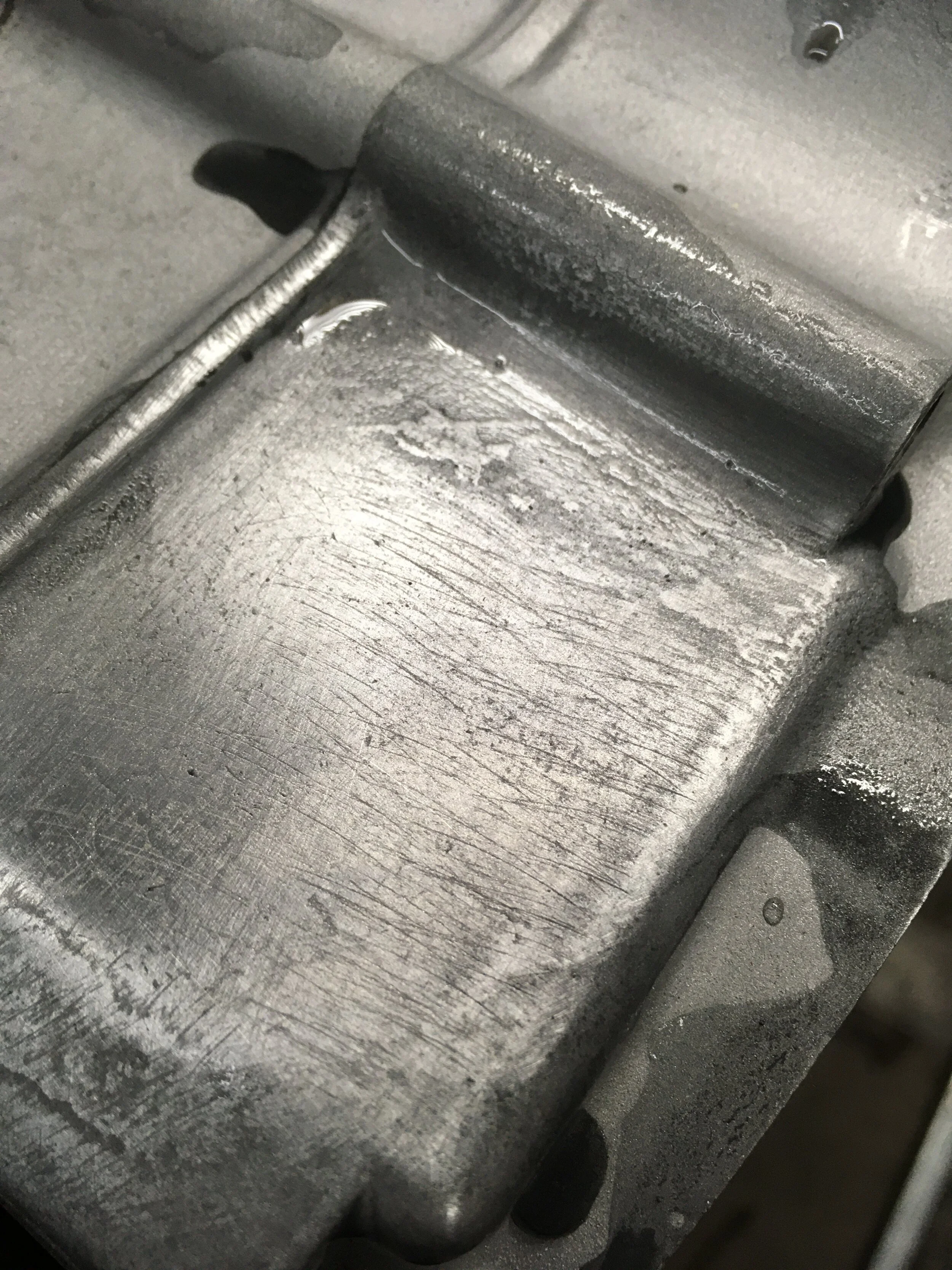
This engine case looks like it was hit by a wire wheel at some point, leaving deep scratches that were removed by hand wet sanding. There are not a lot of shortcuts in metal finishing if you are going to restore a smooth finish removing as little material as possible.

The clutch covers are painted with Cloud Silver paint from Honda. There are new kick and gear shift shafts used on all these engines.

Soon these bikes will be going into some of the bikes in previous posts, and some yet to be seen!

Some of the tools needed. In addition to these, a 6mm and 8mm tap, variable speed drill, an air compressor, and some JES screw drivers are needed. Tools: clutch nut tool, flywheel puller, 17, 14, 10, 9mm sockets, #2 and #3 phillips impact bits, impact driver slip jaw pliers, crescent wrench, needle nose pliers, ring pliers, brass drift, rubber hammer, seal puller.

Somewhere around 60 Honda horizontal engine rebuilds done in the shop, most of them on this stand. You don’t need anything too fancy, but a way to elevate the engine off the bench to clear the shift shaft and kick shaft is needed. A couple pieces of 4x4 lumber will work, or a box shape made of 2x4’s and screws that fits under the outer edges of the engine cases. The main reason this stand was built was to hold the engine firmly while extracting case screws. Because the screws are Phillips type screws usually frozen in the cases, the only reliable method I’ve found to get them out without damage is to use an impact driver, #3 Phillips impact bit, and a considerable amount of downward force. Without a solid base, the irregular surfaces on both sides make this a challenge. The engine will sometimes spin or even fall off the blocks during this process. The stand keeps this from happening and is easy to use, requiring no tools to mount the engine on it.

The actual tear-down is pretty fast and easy. This assembly guide can be done in reverse to disassemble. The time consuming part is cleaning grime and gaskets from the parts. The cases are cleaned first with citrus degreaser, scrapers, towels, and compressed air, removing as much oil and grime as possible. They are washed and scrubbed in kerosene and all gaskets removed. They are then wiped down, blown out, and washed in warm soapy water. They are bead blasted after that, and then blown again, scuffed with fine Scotch-Brite pads, rinsed, and blown. Along the way, any stubborn deposits are scraped off with a razor or pick. Finally, the screw holes are all chased with a tap, and then blown out agian. Obviously, a lot of blowing going on, and some would argue not to do so much in between the steps, but degreasing is tricky in the sense that some processes don’t work as well in different situations. A common example would be thick oil and dirt deposits inside and outside the engine., that are not easily removed by any method, can trap glass bead from blasting, and interfere with trying to chase your threads. In that case, mechanical scraping and wiping are the only sure-fire low tech ways (you can always drop some coin for a large ultrasonic cleaning tank.) The other principle is that each stage in cleaning should bring the minimum amount of contaminants to the next, and blowing does this effectively. A word of caution: eye, face, hand, and ear protection are absolutely necessary for all the blowing, especially if you are using high pressure. Small particles of grime can fly out when blowing and hit you like a sand blaster to the eyes. The ear protection is for the ultra high-pitched whistling that is produced blowing across screw holes.

Once the cases are clean, the oil orifice is drilled out with a 1/16” bit. You can go as high as 2mm in diameter, and as small as 1.5mm. Blow out after drilling.

The transmission bearings need to be pressed in first. The cases can be heated with a small propane torch or heat gun to expand the hole size slightly, and then the bearing can be tapped into place easily with a drift and hammer, making sure only to strike the outer ring of the bearing.

Next, the oil drive shaft and sprocket have to be put into the cases. The fat shaft is the original, the skinny one has been turned to clear the stroker crank, and came as part of a high-volume oil pump kit.

The screw end of the shaft has to pass though the case and into the sprocket. A small rod or screwdriver and a wrench are used to snug up the shaft. The center of either style shaft can be grabbed with vise grips to screw or unscrew it. It does not need to be super tight, the direction the pump rotates keeps it from unscrewing.

The three speed stock tranny with the last parts of the output shaft laid out in order, and the shift drum as it mates up with the shafts. Notice the small thin washer on the left end of the upper shaft, and laying on the far right of the picture. Those special washers are sometimes overlooked, often staying stuck to the engine cases and even lost during disassembly.

The transmission ready for installation. The output shaft on the right of the picture fits into the bearing pressed into the case, the smaller end of the other shaft goes in the bronze bush in the case half, and the shift drum shaft through the top hole in the case.

A small amount of oil needs to be squirted in the bronze bush in the engine case, and the transmission dropped in. If too much oil is used, it will keep the shaft from seating fully. The three main parts of the tranny need to be held together carefully, making sure the thin washer is fitted between the shaft and the bronze bush.

To keep the shifting tight, the shift drum guide pins should be replaced. There is a small hairpin-like clip that holds them in that can be pulled out easily with a metal pick. The pin sometimes gets stuck in the hole, and a strong magnet while wiggling the shift fork will usually do the trick.

Once the tranny is in, the kickstart shaft is placed in the oiled case hole, making sure the arm goes into the groove on the side of the case.

Dropping the crank in requires no tools, and should fit in easily with a little hand pressure and wiggling. The engine case dowels (always use fresh ones, trust me) and center case gasket are the last thing needed before closing the cases back up. Leave the piece of gasket paper that passes across the piston rod until after the case screws are in place.

The right side case should fit on the assembled left side easily, with only slight taps of a rubber mallet needed to coax it together. Look out for the oil drive shaft, transmission shafts and the shift drum to be aligned. They may need slight adjusting to hit their holes right. The remainder of this guide will be in installments, focusing on individual sections of the build for easier future reference. If anyone has questions, please ask on this site so others can perhaps benefit from the Q and A.